When this configuration makes sense
- ✓Long structures and welds spread along the part
- ✓Serving several workstations in one line
- ✓Processes where the arm’s reach alone does not cover the whole part
A cobot on a rail - a larger working area without moving the cell.
An external linear axis enlarges the cell’s working area so it can handle long parts and several workstations. The 2 m track is synchronised with the robot controller. We match the WS cobot model to the kit - any model in the family fits. The actual working area depends on the cell geometry and part fixturing, not on the track length alone.
Track length
2 m
Arm payload
3–30 kg
Arm reach
622–1900 mm
External axis
Linear, synchronised
Plants welding parts longer than the reach of a single cell, or serving several workstations with one robot. The track eliminates moving the cobot by hand between work points - the arm travels to the next workstation within a single, synchronised cycle.
The board shows the process sequence. Below is what decides whether that sequence can be repeated on your structure.
The track length does not add to the arm’s reach. 1900 mm is the cobot’s reach and 2 m is the travel distance - the actual working area is calculated for a specific part and cell.
The rigidity and repeatability of travel come from specific components. They are what distinguish a machine axis from makeshift shifting of the cell.
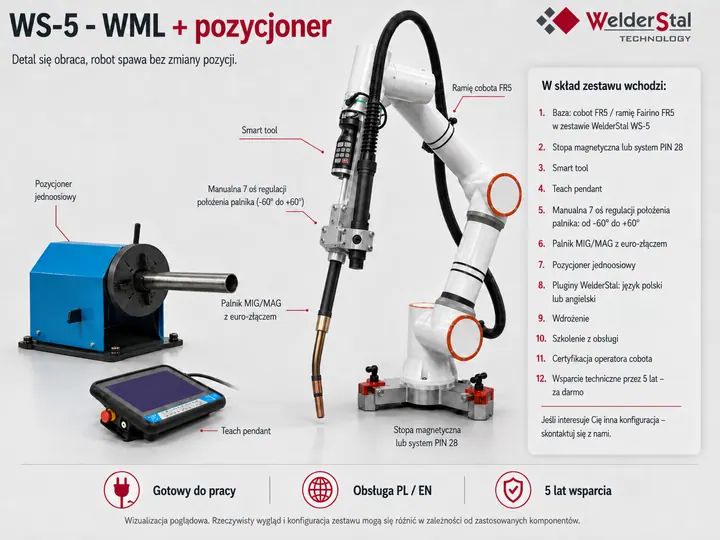
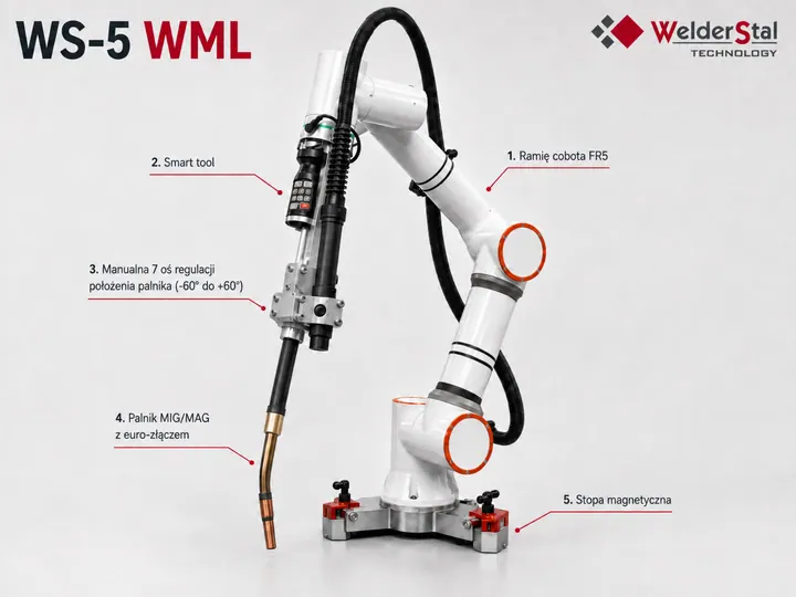
The board shows where each component sits in the kit. The list below is the scope of delivery - stated openly, so that a complete cell is not confused with the cobot arm alone.
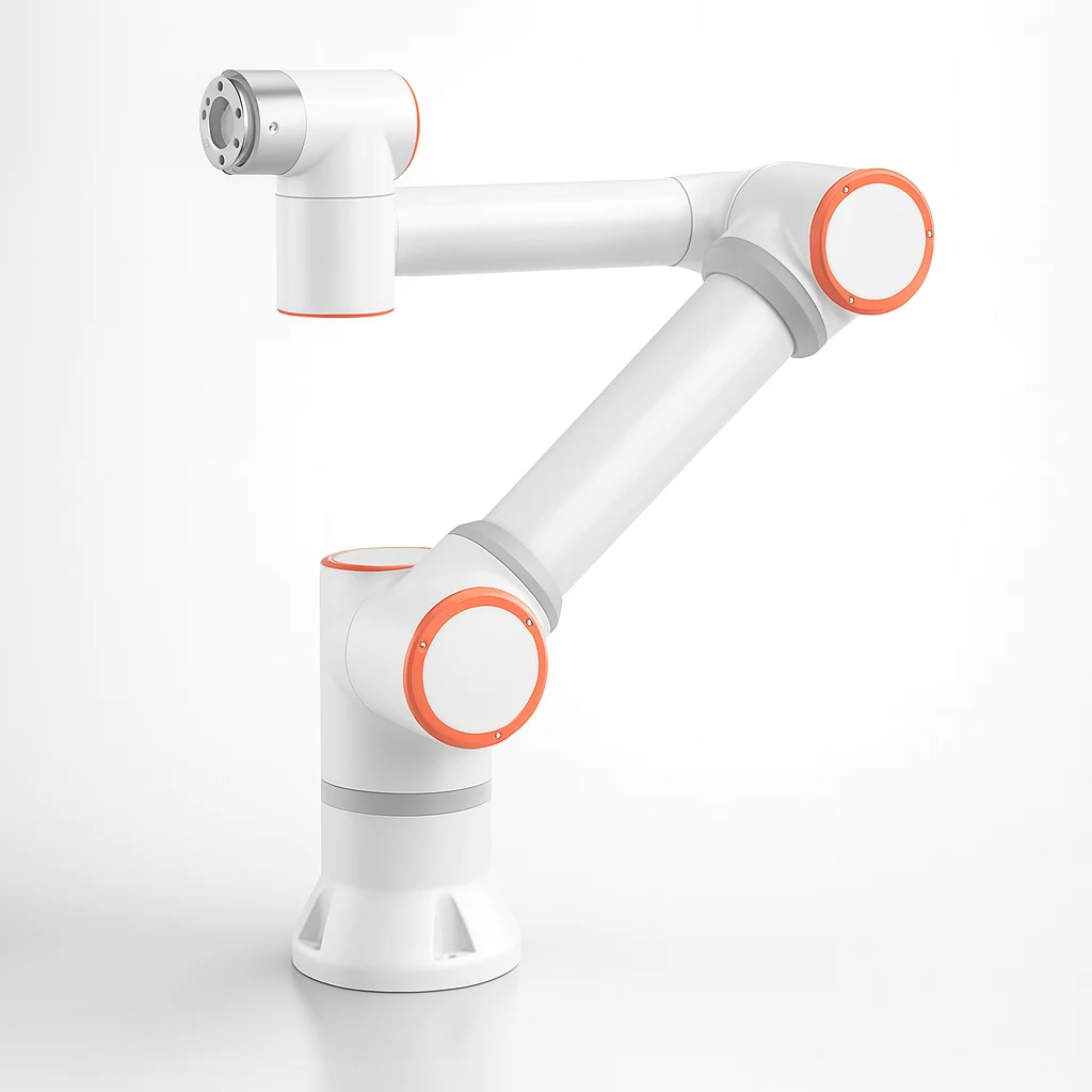
Any cobot in the WS family fits the welding kit. We match the model to the part, reach and cycle time - the rest of the kit stays the same.
WS-3
Fairino FR3
Magnetic foot or PIN 28
WS-3 WMS
Fairino FR3-WMS
PIN 28 system
WS-3 WML
Fairino FR3-WML
PIN 28 system
WS-5
Fairino FR5
Magnetic foot or PIN 28
WS-5 WML
Fairino FR5-WML
PIN 28 system
WS-10
Fairino FR10
PIN 28 system
WS-16
Fairino FR16
PIN 28 system
WS-20
Fairino FR20
PIN 28 system
WS-30
Fairino FR30
PIN 28 system
On the track the cobot is mounted to the carriage, but the same kit also lets you set it up off the track. In that case the base depends on the chosen arm.
The kit with the WS-5 WML arm works on PIN 28 locating pins - with a 1900 mm reach, a magnetic foot cannot hold the cell base. The kit with the WS-5 can also use the magnetic foot, which can be moved to another steel surface without tools. We show both variants on the basic kit page.
Both configurations add an external axis to the cell, but they solve different problems. The difference comes down to what has to move: the cobot or the part.
| Criterion | Linear track | Positioner |
|---|---|---|
| What moves | The cobot along a linear axis | The part on a rotary axis |
| Typical part | Long structures, several workstations in one line | Pipes, sleeves, shafts, flanges |
| Effect on the process | Larger working area along the axis | Welding without refixturing between sides of the part |
| Mechanical base | ITEM profiles, toothed rack and gearbox | Self-centring chuck Ø10–300 mm, continuous rotation |
| Control integration | Synchronised with the robot controller | Synchronised with the robot controller |
Both versions are based on the same arm and the same Welderstal welding plugin, so the choice does not change how the cell is programmed. The difference concerns only the process geometry.
Based on these six pieces of information we check the actual working area, the workstation layout and torch access along the whole travel route.
Part length
Dimension along the travel axis
Number of workstations
How many workstations one cobot is to serve
Space for travel
Free space along and around the track
Weld layout
Distribution of welds along the structure
Part fixturing
Fixtures, datum surfaces and tolerances
Material and process
Thickness, weld type, MAG parameters
Give us the part length, number of workstations, space available along the track and the weld layout. On that basis we will calculate the actual working area and check the cell geometry.
Send part details for selection